If you search for “raspberry pi ph meter” you’ll quickly learn that there are very few affordable options when it comes to digitally monitoring the pH of your nutrient solution. For a while Atlas Scientific dominated the search results, but I believe their kit was around $200 at the time. The kit has since come down to $164, but for someone like me that’s still a bit out of my price range.
The problem with the Raspberry Pi is that it has no analog inputs and pH meters are analog for the most part. I like the Raspberry Pi as it’s a one stop shop, sure I could have used a computer that has analogs out of the box, but then how would I upload the information to a remote MySQL server? I’d have to expand that board.
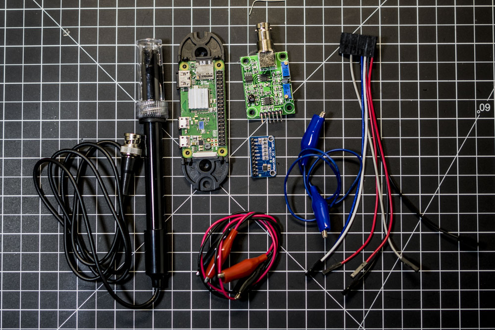
Anyway here is a list of parts I used for this project with the three affiliates I use. Obviously AliExpress is the winner, but if you’re in a time crunch and have the extra money the other two are the exact same things.
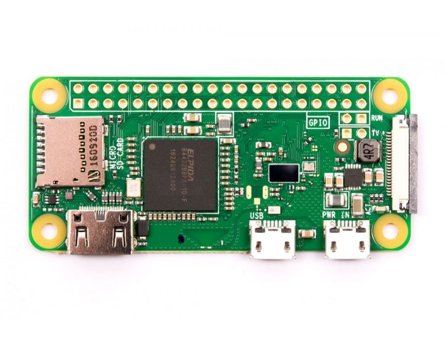
** Note: I am using a Raspberry Pi Zero W, this schematic will work with any 40 pin header Raspberry Pi.
| Parts used in this Guide (Shipping not included as this varies) | |||
|---|---|---|---|
 |
 |
 |
|
| Raspberry Pi Zero W | $18.09 | $19.98 | $21.49 |
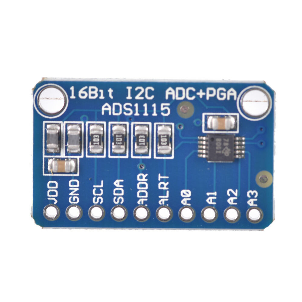
| ADS1115 | $1.61 | $1.79 | $6.99 |
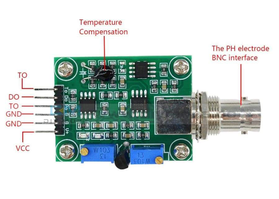
| PH4502C + pH Probe | $10.47 | $14.53 | $37.99 |
| pH Reference Solution | $0.95 (powder) | $17.95 | $18.52 |
| Total: | $30.17 | $54.25 | $82.38 |
Step 1: Wiring
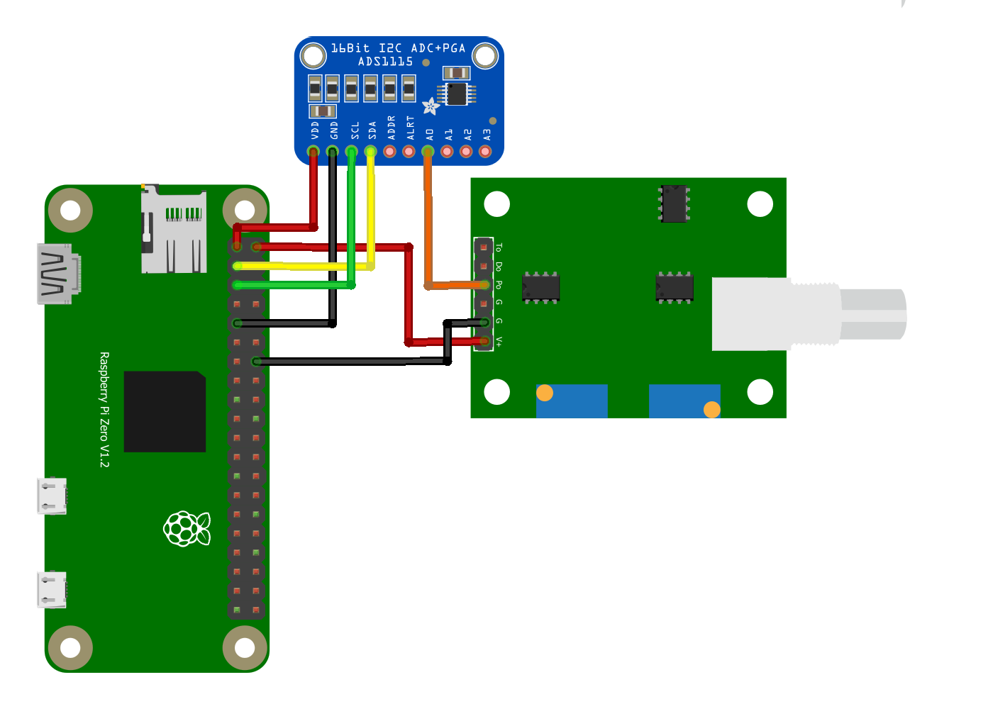
- RPi pin 1 (3.3V) to ADS1115 pin VDD
- RPi pin 2 (5V) to PH4502C pin V+
- RPi pin 3 (SDA) to ADS1115 pin SDA
- RPi pin 5 (SCL) to ADS1115 pin SCL
- RPi pin 8 (GND) to PH4502C pin G (Analog GND closest to V+)
- RPi pin 9 (GND) to ADS115 pin GND
- ADS1115 pin A0 to PH4502C pin Po
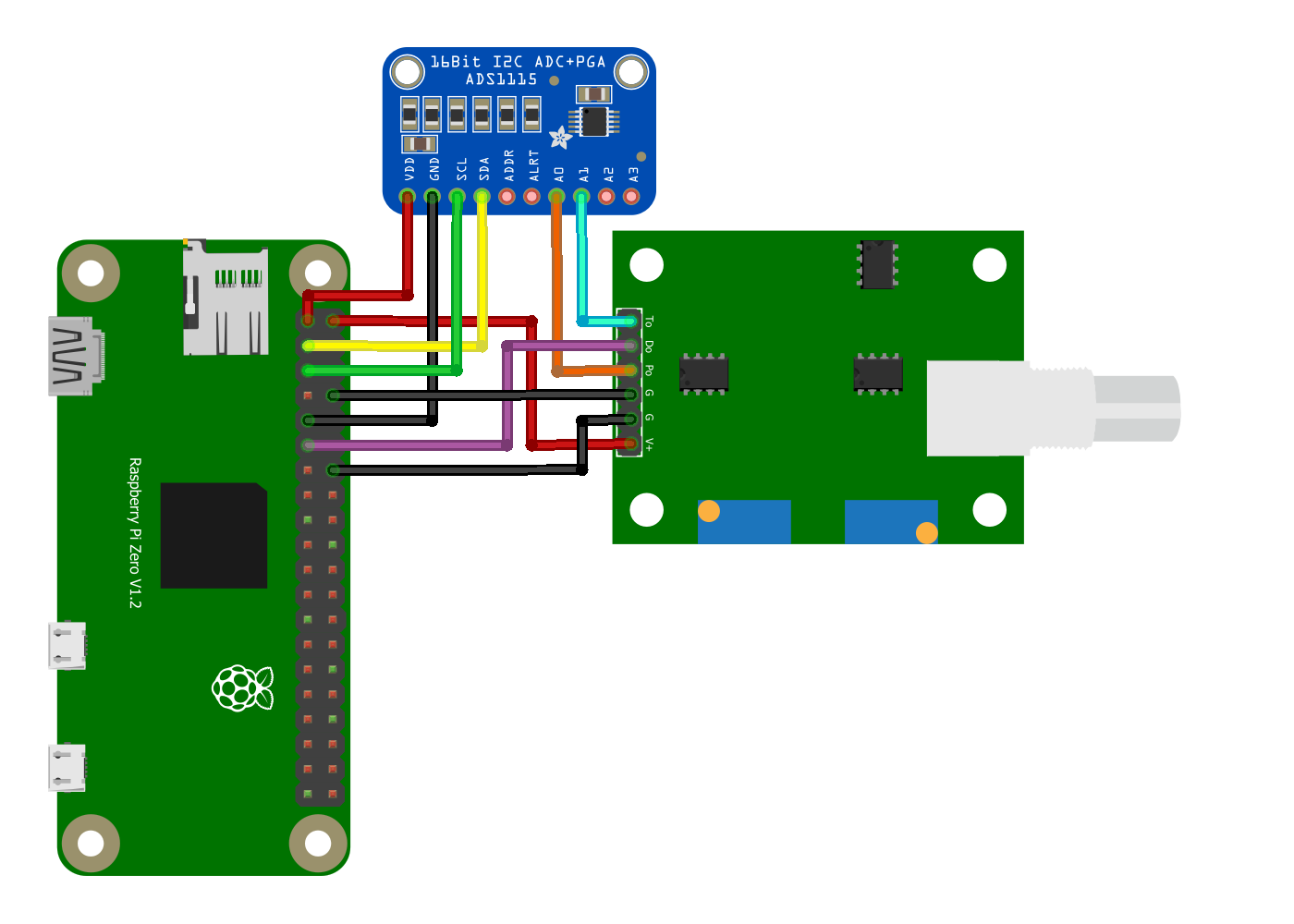
Optional Setup
There are some optional pins on the PH4502C: To, Do, and G (digital, the G pin furthest from V+). You do not need these pins unless you want a digital signal for the pH limit or the analog temperature sensor as the PH4502C has built in temperature compensation. I do use the temperature sensor built into the pH probe since it’s already there.
- RPi pin 11 (GPIO 17) to PH4502C pin Do (Optional Digital pH Limit)
- RPi pin 14 (GND) to PH4502C pin G (Digital GND)
- ADS1115 pin A1 to PH4502C pin To
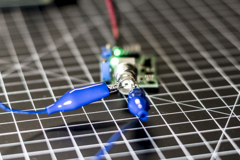
Step 2: Adjusting the PH4502C Voltage Offset
So the idea behind this step is that that the PH4502C Po voltage oscillates between positive and negative values. We only want positive values for the ADC to convert. To remedy this we force a pH “reading” of 7.0 by shorting the BNC connector. To short the BNC take a metal paper clip and insert it down the center female input on the connector and connect one end of alligator clips to the paper clip and the other end to the outer metal casing of the BNC connector.
Once you have shorted the BNC you can run the following script, which I put way to much thought into. Once you start this script and dial it in to ~2.5 volts, you can leave it running for Step 3.
Step 3: Mapping the the voltage to pH readings
In this step we will map two known pH measurements to their respective reported voltages. To do this step you either need some pH calibration solution, or you can use another substance of known pH; however, I prefer pH calibration solution.
I use General Hydroponics Standard Reference Solution pH 4.01 and pH 7.0. You will want some distilled, purified, or some sort of deionized water. Use this water to rinse the probe between pH measurements.
Once you have your solutions ready, the script from Step 2 should still be reporting a ~2.5 voltage connect the pH probe to the BNC to take measurements. Place the probe in both the pH 4.01 solution and the pH 7.0 solution (rinsing in between) and record their output voltages. It can take up to 2 minutes for the sensor to stabilize, so give it time in each solution.
Now that you have voltages for 4.01 and 7.00 reference solutions, use y = mx + b to solve the linear equation and map the range.
In my situation, pH 4.01 reported 3.11 volts (3.11,4.01) and pH 7.0 reported 2.58 volts (2.58, 7.0). If y = pH and x = voltage we can solve for m by y2-y1⁄x2-x1.
7.0-4.01⁄2.58-3.11 = 2.99/-0.53 = –5.641509 = m
Once we have m we simply substitute it back in to one set, we’ll use pH 4.01. 4.01 = -5.641509(3.11) + b. Then solve for b = 21.55509299. The final formula is pH = -5.641509(voltage) + 21.55509299.
External Sources
[1] https://raspberrypi.stackexchange.com/questions/96653/ph-4502c-ph-sensor-calibration-and-adc-using-mcp3008-pcf8591-and-ads1115
[2] https://www.botshop.co.za/how-to-use-a-ph-probe-and-sensor/
[3] https://scidle.com/how-to-use-a-ph-sensor-with-arduino/
Hi, you have this
In my situation, pH 4.01 reported 2.52 volts (3.11,4.01) and pH 7.0 reported 3.51 volts (2.58, 7.0).
Where did the 3.11 value come from if the reported value was 2.52?
And where did the 2.58 value come from if the reported value was 3.51?
I believe that was a mistake on my part. I need to correct those numbers. Thanks for pointing it out!
Thanks for these instructions – I created a modified version of your code that outputs to a file (which is read by another app) and runs as a startup script on a raspberry pi.
Awesome, glad I could contribute!
Awesome! I’m glad I could help.
ADS1115 datasheet tells that the absolute maximum voltage for analog inputs is VDD+0.3V. The PH sensor is outputting values between 0-5V while ADC VDD is 3.3v. How is this possible?
Jerry, In step 2 we normalized the PH probe from -2.5 to 2.5v. This prevents the voltage from going above 3.3V.
I want to know how to fix this. ads = ADS1115(i2c)
AttributeError : module ‘ adafruit_ads1115’ has no attribute ‘ADS1115’
Make sure you have the right module from adafruit.
I checked that there is a module.
I would like to know how do you install the module.
You have to install this library: https://github.com/adafruit/Adafruit_CircuitPython_ADS1x15
I would like to know if the value obtained is 3.71 v, then what is PH? How do you compare or calculate the value?
Hallo,
what is the range of the offset? After shorten the BNC and messure the output voltage I can adjust in a range of 2.56 V up to VCC is this right or is my part broken?
Thanks a lot
Peter
Hi,
I have a project and trying to start out as a complete novice. Is it possible to run this using a Pico? The plan is to use solar power to run a Raspberry with pH sensor, temperature sensor and water pump.
Yes, you’d have to re-write everything for pico… pico does have built in ADCs so you can really remove that.
Hey Andrew,
“Once you have your solutions ready, the script from Step 2 should still be reporting a ~2.5 voltage connect the pH probe to the BNC to take measurements”
How you connect the pH probe to the BNC with the paper clip on it? should i remove the clip?
Wag, once you calibrate the pH Probe you can remove the paper clip.
for some reason 7.0PH @ 25c was 3.67v and 3.2PH @ 25c was 4.1v. This doesn’t seem like I’m doing this right.
Hey, you are doing it right in my opinion. My values for ph4,7,9 are: pH4.0 = 3.64, pH7.0 = 3.32 and pH_9 = 3.12. The values in my case are not linear so for the conversion to pH I had to use the polynomial function. I used https://chat.openai.com/chat as a helping hand.
Think I solved that. 2.63 V is 5.2% higher than 2.5 V. So I substracted 5.2% of the V values for my PH4.0 og PH7.0 readings. I get the same readings with my manual measuring sticks 🙂
Hello,
Thank you so much for your tutorial. I just had one question- why do you “ground” the BNC connector in step 2? Why should the ADC only get positive values?
Where do the ‘board’ and ‘busio’ modules come from?
Gary,
This should help you out: https://learn.adafruit.com/arduino-to-circuitpython/the-board-module
I think you’re going to have a hard time finding a sensor that can tell you water composition.
please can someone help me it says 4.1v all the time
i short the bnc and 4.1v
i connect probe and 4.1v